ASTM B407 Nickel-Iron-Chromium Alloy Seamless Pipe Tube
ASTM B407 Nickel Alloy Seamless Tubes covers UNS N08120, UNS N08800, UNS N08801, UNS N08810, UNS N08811, UNS N08890, and UNS N06811 in the form of cold-worked and hot-finished annealed seamless pipe and tube. Alloys UNS N08800 and UNS N06811 are normally employed in service temperatures up to and including 1100°F (593°C). Alloys UNS N08120, UNS N08810, UNS N08811, and UNS N08890 are normally employed in service temperatures above 1100°F (593°C) where resistance to creep and rupture is required, and they are annealed to develop controlled grain size for optimum properties in this temperature range.
The values stated in inch-pound units are to be regarded as the standard. The values given in parentheses are for information only.
The following safety hazards caveat pertains only to the test method portion, Section 13, of this specification. This standard does not purport to address all of the safety concerns, if any, associated with its use. It is the responsibility of the user of this standard to become familiar with all hazards including those identified in the appropriate Material Safety Data Sheet (MSDS) for this product/material as provided by the manufacturer, to establish appropriate safety and health practices, and determine the applicability of regulatory limitations.
2. Referenced Documents
2.1 ASTM Standards:
B 880 Specification for General Requirements for Chemical Check Analysis Limits for Nickel, Nickel Alloys and Cobalt Alloys
E 8 Test Methods for Tension Testing of Metallic Materials
E 18 Test Methods for Rockwell Hardness of Metallic Materials
E 29 Practice for Using Significant Digits in Test Data to Determine Conformance with Specifications
E 112 Test Methods for Determining Average Grain Size
E 140 Hardness Conversion Tables for Metals Relationship Among Brinell Hardness, Vickers Hardness, Rockwell Hardness, Superficial Hardness, Knoop Hardness, and Scleroscope Hardness
E 426 Practice for Electromagnetic (Eddy-Current) Examination of Seamless and Welded Tubular Products, Austenitic Stainless Steel and Similar Alloys
E 571 Practice for Electromagnetic (Eddy-Current) Examination of Nickel and Nickel Alloy Tubular Products E 1473 Test Methods for Chemical Analysis of Nickel, Cobalt, and High-Temperature Alloys
3. Terminology
3.1 Definitions:
3.1.1 average diameter, n—average of the maximum and minimum outside diameters, or the maximum and minimum inside diameters, as determined at any one cross section of the tube.
3.1.2 pipe, n—seamless tube conforming to the particular dimensions commercially known as standard pipe sizes (see Table X3.1).
3.1.3 tube, n—hollow product of round or any other cross section having a continuous periphery.
4. Ordering Information
4.1 Orders for material to this specification should include information with respect to the following:
4.1.1 Alloy (Table 1).
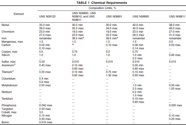
A Iron shall be determined arithmetically by difference.
B Alloy UNS N08800: 0.10 max. Alloy UNS N08810: 0.05–0.10. Alloy UNS N08811: 0.06–0.10.
C Alloy UNS N08811: Al + Ti, 0.85–1.20.
4.1.2 Condition Temper (Table 2 and Table X3.1, and Appendix X2 and Appendix X3).
A For properties of small-diameter and light-wall tubing, see Table X3.1.
4.1.3 Finish (Table X1.1 and Table X3.2).
4.1.4 Dimensions:
4.1.4.1 Tube—May be specified in two dimensions only (length excepted) as follows: Outside diameter and average or minimum wall, inside diameter and average wall, or outside diameter and inside diameter.
NOTE 1—Tube produced to outside diameter and minimum wall may be furnished upon agreement between the manufacturer and the purchaser.
4.1.4.2 Pipe—Standard pipe size and schedule (Table X3.1).
4.1.5 Fabrication Details—Not mandatory but helpful to the manufacturer:
4.1.5.1 Cold Bending or Coiling.
4.1.5.2 Hot Forming.
4.1.5.3 Welding or Brazing—Process to be employed.
4.1.5.4 Pressure Requirements—Test pressure if other than required by 7.3.
4.1.5.5 Machining—Indicate finished size and length in which to be machined and whether to be chucked to outside diameter or inside diameter.
4.1.5.6 Ends—Plain ends cut and deburred will be furnished. If threaded ends or ends beveled for welding are desired, give details.
4.1.6 Certification—State if certification or a report of test results is required (Section 16).
4.1.7 Samples for Product (Check) Analysis—State whether samples for product (check) analysis should be furnished (6.2).
4.1.8 Purchaser Inspection—If the purchaser wishes to witness tests or inspection of material at place of manufacture, the purchase order must so state indicating which tests or inspections are to be witnessed (Section 14).
4.1.9 Small-Diameter and Light-Wall Tube—(Converter Sizes) (Table X3.2).
4.1.10 Optional Requirement—Hydrostatic or Nondestructive Eddy Current Testing (see 7.3.3).
5. Materials and Manufacture
5.1 Heat Treatment—The final heat treatment of UNS N08120 shall be 2150°F (1177°C) minimum, UNS N08810,2050°F (1121°C) minimum, UNS N08811, UNS N08890, 2100°F (1149°C) minimum, and UNS N06811, 1920°F (1050°C) minimum.
6. Chemical Composition
6.1 The material shall conform to the composition limits specified in Table 1.
6.2 If a product (check) analysis is performed by the purchaser, the material shall conform to the product (check) analysis variations in Specification B 880.
7. Mechanical Properties and Other Requirements
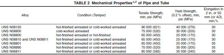
7.1 Mechanical Properties—The material shall conform to the mechanical properties specified in Table 2.
7.2 Grain Size—Annealed UNS Alloys N08120, N08810, N08811, and UNS N08890 shall conform to an average grain size of ASTM No. 5 or coarser.
7.3 Hydrostatic Test:
7.3.1 Each pipe or tube with an outside diameter 1⁄8 in. (3.2 mm) and larger, and tubes with wall thickness of 0.015 in. (0.38 mm) and over shall be tested by the manufacturer to an internal hydrostatic pressure of 1000 psi (6.9 MPa) provided that the fiber stress calculated in accordance with the following equation does not exceed the allowable fiber stress, S, indicated below. The pipe or tube shall show no evidence of leakage.
P=2St/D
where:
P = hydrostatic test pressure, psi (MPa),
S = allowable fiber stresses, for material in the condition, as follows:
Cold-drawn annealed or hot-finished annealed alloy UNS N08120 22 500 psi 155 (MPa)
Cold-drawn annealed alloy UNS N08800 and all alloy UNS N08890 18 700 psi (130 MPa)
Hot-finished as hot-finished, or hot-finished annealed, alloy UNS N08800 16 600 psi (115 MPa)
Cold-drawn annealed or hot-finished annealed alloys UNS N08810, UNS N08811, and UNS N08801 16 600 psi (115 MPa)
Cold-drawn annealed or hot-finished annealed alloy UNS N06811 21 200 psi (145 MPa)
t = minimum wall thickness, in. (mm), equal to the specified average wall minus the permissible minus wall tolerance, Table 3, or the specified minimum wall thickness, and
D = outside diameter of the tube, in. (mm).
7.3.2 When so agreed upon between the manufacturer and purchaser, pipe or tube may be tested to 11⁄2 times the allowable fiber stress given in 7.3.1.
7.3.3 Each pipe or tube shall be subjected to the hydrostatic test, or, in lieu of this test, a nondestructive eddy current test may be used at the manufacturer’s option. If eddy current testing is used, the following test method would apply:
7.3.3.1 Eddy-Current Testing—Testing shall be conducted in accordance with Practices E 426 or E 571. The eddy-current examination referenced in this specification has the capability of detecting significant discontinuities, especially of the short abrupt type.
(1) Unless otherwise specified the calibration standard shall contain, at the option of the manufacturer, any one of the following discontinuities to establish a minimum sensitivity
level for rejection. The discontinuity shall be placed in the weld if visible.
(2) Drilled Hole—A hole not larger than 0.031 in. (0.79 mm) in diameter shall be drilled radially and completely through the wall, care being taken to avoid distortion of the material while drilling.
(3) Transverse Tangential Notch—Using a round file or tool with a 1⁄4 in. (6 mm) diameter, a notch shall be filed or milled on the tube outside diameter tangential to the surface and transverse to the longitudinal axis of the material. Said notch shall have a depth not exceeding 121⁄2 % of the specified wall thickness of the material, or 0.004 in. (0.10 mm), whichever is greater.
7.3.3.2 Calibration Frequency—The frequency of calibration checks shall be as follows:
(1) At the beginning of each production run or log.
(2) After every 4 h or less during testing.
(3) At the end of each production run or lot.
(4) At any time malfunctioning is suspected, or the equipment has been left unattended.
(5) If, during any check, the equipment fails to pick up the standard defects in the calibration standard, the instrument test must be recalibrated and all material tested since the last check shall be reexamined.
7.3.3.3 Acceptance and Rejection—Material producing a signal equal to or greater than the calibration imperfection shall be subject to rejection.
(1) Test signals produced by imperfections that cannot be identified or produced by cracks or crack-like imperfections shall result in rejection of the tube, subject to rework, and retest.
(2) If the imperfection is judged as not fit for use, the tube shall be rejected, but may be reconditioned and retested providing the dimensions requirements are met. To be accepted, retested material shall meet the original electric test requirements.
(3) If the imperfection is explored to the extent that it can be identified and the pipe or tube is determined to be fit for use, the material may be accepted without further test providing the imperfection does not encroach on the minimum wall thickness.
7.4 Annealing Temperature—Alloy UNS N08120 shall be annealed at 2150°F (1177°C) minimum, and UNS N08810 at 2050°F (1120°C) minimum.
8. Dimensions and Permissible Variations
8.1 Diameter and Wall Thickness:
8.1.1 The permissible variations in the outside and inside diameter and wall thickness of pipe and tube shall not exceed those prescribed in Table 3 and Table X3.2, as applicable.
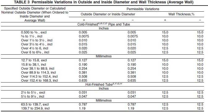
A The permissible variations in this table apply to individual measurements, including out-of-roundness (ovality), except for the following conditions.
1) Thin-Wall Pipe and Tube—For thin-wall pipe and tube having a nominal wall thickness of 3 % or less of the nominal outside diameter, in all conditions (temper), the mean outside diameter or mean inside diameter shall conform to the permissible variations of this table, and individual measurements (including ovality) shall conform to the plus and minus values of this table, with the values increased by 0.5 % of the nominal outside diameter.
2) Annealed Pipe and Tube Over 41⁄2 in. (114.3 mm) in Nominal Outside Diameter—For annealed pipe and tubing over 41⁄2 in. (114.3 mm) in nominal outside diameter with a nominal wall thickness greater than 3 % of the nominal outside diameter, the mean outside diameter or mean inside diameter shall conform to the permissible variations of this table, and individual measurements shall not exceed twice the permissible variations of this table.
B For pipe and tube, in all tempers, with an inside diameter of less than 1⁄2 in. (12.70 mm) which cannot be successfully drawn over a mandrel, the inside diameter shall be governed by the outside diameter and the wall thickness variations.
C For pipe and tube in all tempers with an inside diameter less than 50 % of the outside diameter, which cannot be successfully drawn over a mandrel, the inside diameter may vary over or under by an amount equal to 10 % of the nominal wall thickness and the wall thickness may vary 615 %.
D Eccentricity—The variation in wall thickness in any one cross section of any one cold-finished pipe or tube shall not exceed 610 % of the actual (measured) average wall of that section (defined as the average of the thickest and the thinnest wall in that section).
E For tube 5 in. (127.0 mm) and under in outside diameter the tolerance on the outside diameter applies for individual measurements and includes ovality. For tubes over 5 in. (127.0 mm) in outside diameter the mean outside diameter shall conform to the permissible variations of this table and individual measurements shall not exceed twice the permissible variations of this table.
F The diameter tolerances for tube with machined outside and inside diameters shall be +0.031 in. (0.787 mm), −0 for the outside diameter and +0, − 0.062 in. (1.57 mm) for the inside diameter.
G If tube is specified as minimum wall, the tolerance shall be +28.5 %, −0.
H The wall thickness tolerance includes eccentricity tolerance up to 612.5 %.
8.1.2 Permissible variations given in Table 3 and Table X3.2 are applicable only to two dimensions. Thus, if outside diameter and wall are specified, the inside diameter may not conform to the permissible variations shown. Similarly, if outside diameter and inside diameter are specified, the wall may not conform to the permissible variations shown.
8.2 Length—When pipe or tube is ordered cut-to-length, the length shall not be less than that specified, but a variation of A The permissible variations in this table apply to individual measurements, including out-of-roundness (ovality), except for the following conditions.
1) Thin-Wall Pipe and Tube—For thin-wall pipe and tube having a nominal wall thickness of 3 % or less of the nominal outside diameter, in all conditions (temper), the mean outside diameter or mean inside diameter shall conform to the permissible variations of this table, and individual measurements (including ovality) shall conform to the plus and minus values of this table, with the values increased by 0.5 % of the nominal outside diameter.
2) Annealed Pipe and Tube Over 41⁄2 in. (114.3 mm) in Nominal Outside Diameter—For annealed pipe and tubing over 41⁄2 in. (114.3 mm) in nominal outside diameter with a nominal wall thickness greater than 3 % of the nominal outside diameter, the mean outside diameter or mean inside diameter shall conform to the permissible variations of this table, and individual measurements shall not exceed twice the permissible variations of this table.
B For pipe and tube, in all tempers, with an inside diameter of less than 1⁄2 in. (12.70 mm) which cannot be successfully drawn over a mandrel, the inside diameter shall be governed by the outside diameter and the wall thickness variations.
C For pipe and tube in all tempers with an inside diameter less than 50 % of the outside diameter, which cannot be successfully drawn over a mandrel, the inside diameter may vary over or under by an amount equal to 10 % of the nominal wall thickness and the wall thickness may vary 615 %.
D Eccentricity—The variation in wall thickness in any one cross section of any one cold-finished pipe or tube shall not exceed 610 % of the actual (measured) average wall of that section (defined as the average of the thickest and the thinnest wall in that section).
E For tube 5 in. (127.0 mm) and under in outside diameter the tolerance on the outside diameter applies for individual measurements and includes ovality. For tubes over 5 in. (127.0 mm) in outside diameter the mean outside diameter shall conform to the permissible variations of this table and individual measurements shall not exceed twice the permissible variations of this table.
F The diameter tolerances for tube with machined outside and inside diameters shall be +0.031 in. (0.787 mm), −0 for the outside diameter and +0, − 0.062 in. (1.57 mm) for the inside diameter.
G If tube is specified as minimum wall, the tolerance shall be +28.5 %, −0.
H The wall thickness tolerance includes eccentricity tolerance up to 612.5 %.
12. Specimen Preparation
12.1 Tension test specimens shall be taken from material in the final condition (temper) and tested in the direction of fabrication.
12.2 Whenever possible, all pipe and tube shall be tested in full tubular size. When testing in full tubular size is not possible, longitudinal strip specimens, or the largest possible round specimen, shall be used. In the event of disagreement when full tubular testing is not possible, a longitudinal strip specimen with reduced gage length as contained in Test Methods E 8 shall be used.
13. Test Methods
13.1 The chemical composition, mechanical, and other properties of the material as enumerated in this specification shall be determined, in case of disagreement, in accordance with the following methods:
Test Method ASTM Designation
Chemical Analysis E 1473 Tension E 8
Rounding Procedure E 29
Rockwell Hardness E 18
Grain Size E 112
Hardness Conversion E 140
13.2 The measurement of average grain size may be carried out by the planimetric method, the comparison method, or the intercept method described in Test Methods E 112. In case of dispute, the “referee” method for determining average grain size shall be the planimetric method.
13.3 For purposes of determining compliance with the specified limits for requirements of the properties listed in the following table, an observed value, or a calculated value, shall be rounded as indicated below, in accordance with the rounding method of Practice E 29:
Test Methods
Rounded Unit for Observed or Calculated Value Chemical composition, hardness, and tolerances (when expressed in decimals) nearest unit in the last right-hand place of figures of the specified limit
Tensile strength, yield strength nearest 1000 psi (6.9 MPa)
Elongation nearest 1 %
Grain size:
0.0024 in. (0.060 mm) or larger nearest multiple of 0.0002 in. (0.005 mm)
less than 0.0024 in. (0.060 mm) nearest multiple of 0.0001 in. (0.002 mm)
14. Inspection
14.1 Inspection of the material shall be made as agreed upon between the manufacturer and the purchaser as part of the purchase contract.
15. Rejection and Rehearing
15.1 Material not conforming to this specification or to authorized modifications will be subject to rejection.
15.2 Samples tested in accordance with this specification that represent rejected material shall be preserved for not less than 3 weeks from the date of the test report. In case of dissatisfaction with the results of the tests, the manufacturer may make claim for a rehearing within that time.
16. Certification
16.1 When specified in the purchase order or contract, a manufacturer’s certification shall be furnished to the purchaser stating that material has been manufactured, tested, and inspected in accordance with this specification, and that the test results on representative samples meet specification requirements. When specified in the purchase order or contract, a report of the test results shall be furnished.
17. Product and Package Marking
17.1 Product Marking—The name or brand of the manufacturer, the trade name of the material or UNS number, the letters ASTM, the specification number, heat number and nominal size shall be legibly marked on each piece 3⁄4 in. (19.1 mm) and over in outside diameter, provided the length is not under 3 ft (914 mm). The material marking shall be by any method which will not result in harmful contamination.
17.1.1 For material less than 3⁄4 in. (19.1 mm) in outside diameter and material under 3 ft (914 mm) in length, the information in 17.1 shall be either stenciled or marked on a tag securely attached to the bundle or box in which the material is shipped.
17.2 Package Marking—Each bundle or shipping container shall be marked with the name or brand of the manufacturer, the trade name of the material or UNS number, the letters ASTM, the specification number, heat number, condition and nominal size, net weight, consignor and consignee address, contract or order number, or other such information as may be defined in the contract or order.

 ASTM B407 Standard Specification for Nickel-Iron-Chromium Alloy Seamless Pipe and Tube ASTM B407 Standard Specification for Nickel-Iron-Chromium Alloy Seamless Pipe and Tube
|