C360 C36000 Brass
This paper is intended as a brief primer on Free Cutting Brass, UNS C36000. Free-Cutting Brass, which many people know by it's traditional name, CDA Alloy 360, is the most important commercial copper alloy, surpassing all but copper itself in terms of annual consumption. Exact quantities are difficult to calculate, but over 600 million pounds of Free Cutting Brass are consumed in the U.S. each year.
Despite this large usage, brass is underutilized as an automatic screw machine feedstock. Perhaps ten times more leaded steel is used than Free Cutting Brass. In general industrial products, and brass screw machine parts are scarce enough today in automotive vehicles to be listed as an endangered species.
Are the properties of leaded steel uniquely needed when making screw-machine parts? Is leaded steel so cheap that brass can only be justified for a small number of specialty products? Or, as some suspect, is steel specified more out of tradition than actual need... or simply in error based on off-the-shelf cost considerations that neglect actual net cost?
CDA surveyed engineers, designers, purchasing agents and automatic screw machine operators to find the answers.
In short, CDA found that while most automotive designers and engineers know a little bit about Free Cutting Brass, few individuals surveyed know enough about the material to consider specifying it for automotive products. Clearly, the brass industry is facing an information gap. Here, then, is some basic information about Free-Cutting Brass: how it is made, what it's properties are and what advantages it offers to automotive designers.
To our surprise, we learned that:
- Tradition dominates material selection, especially in the automotive industry. Of 25 screw machine parts randomly selected by one automaker, 23 had always been specified in leaded steel, yet no one could explain why;
- Most designers, engineers and purchasing agents are convinced brass is too expensive for simple products. Reason: brass's raw materials costs appear to be more than twice as high as steel (although few are aware that finished brass parts cost less);
- Some designers think brass's mechanical properties are inadequate, even though leaded steel is relatively weak and can't be heat treated;
Extra cost for corrosion protection (plating) is taken for granted.
Brass is the term used for alloys of copper and zinc in a solid solution. Brass has a yellow color, somewhat similar to gold and is resistant to tarnishing.
C36000 Brass Seamless Tubes Standard Specification:
| COUNTRY |
STANDARD |
NAME |
| ASTM |
ASTM B111 |
Copper and Copper-Alloy Seamless Condenser Tubes and Ferrule Stock |
| GB/T |
GB/T8890 |
Seamless Copper Alloy Heat Exchanger Tubes |
| BS |
BS2871 |
Copper and Copper Alloys Tubes |
| JIS |
JIS H3300 |
Copper and Copper Alloy-Seamless Pipes and Tubes |
| DIN |
DIN1785 |
Wrought Copper and Copper Alloy Tubes for Condensers and Heat Exchangers |
C360 Free Cutting Brass Most common brass, excellent high speed machining operations and superior thread rolling and knurling characteristics. Easily soldered and brazed and has very good resistance to corrosion.
Fair to excellent corrosion resistance. Excellent machinability. Fabricated by machining, roll threading and knurling.
Applications: gears, pinions, automatic high-speed screw machine parts.
C36000 Free Machining Brass / Free Cutting Brass is ideally suited for high speed machining operations with its superior machinability, thread rolling and knurling characteristics. Its machinability rating of 100 is standard against which all other copper alloys are rated. It is easily soldered or brazed and has good resistance to corrosion.
Typical Application of C36000 CDA 360 / CuZn36Pb3 - Free Machining Brass
- ARCHITECTURE: Terrazzo Strip
- AUTOMOTIVE: Sensor Bodies, Threaded Inserts for Plastic, Fluid Connectors, Thermostat Parts
- BUILDERS HARDWARE: Lock Bodies, Hardware, Fittings
- CONSUMER: Hot Combs (to Straighten Hair)
- FASTENERS: Bolts, Nuts, Screws
- INDUSTRIAL: Faucet Components, Pneumatic Fittings, Fluid Connectors, Automatic Screw Machine Parts, Unions, Adapters, Screw Machine Products, Gauges, Valve Seats, Valve Trim, Valve Stems, Nozzles, Pinions, Gears
- PLUMBING: Plumbers' Brass Goods, Faucet Stems, Faucet Seats, Plumbing Fittings
360 Brass Free Machining Brass
Free Machining brass is the most commonly used of the brass rod and bar items. The presence of lead in the alloy creates a highly machinable material that can easily be cut and shaped into whatever you need. It is not so good, however, at forming operations.
| C360 Free Machining Brass |
| Minimum Properties |
Ultimate Tensile Strength, psi |
58,000 |
| Yield Strength, psi |
45,000 |
| Elongation |
25% |
| Rockwell Hardness |
B78 |
| Chemistry |
Copper (Cu) |
60 - 63% |
| Zinc (Zn) |
35.5% |
| Iron (Fe) |
0.35% min |
| Lead (Pb) |
2.5 - 3.7% |
Structure, Properties
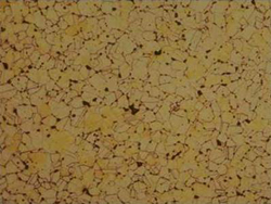 Figure 5 Figure 5
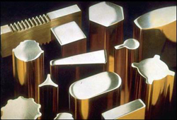 Figure 6 Figure 6C36000 is a so-called duplex brass, that is, it's microstructure contains a two-phase alpha-beta structure. This can be seen in the photomicrograph shown in Figure 5. The duplex structure combines moderately high strength with good corrosion resistance in industrial and automotive environments.
Free-Cutting Brass is almost always supplied in the half-hard (HO2) temper for screw machine applications, although soft annealed (060) and Hard (HO4) tempers are also available for special-purpose applications. Most screw machine feedstock is sold in round and hexagonal rod in sizes ranging from 12 to 38 mm (to 1 1/2 in). Smaller and larger-diameter rods, as well as octagonal rod, square and rectangular bar, flats and a wide variety of standard and custom shapes are also available,Figure 6. Domestically produced products must conform with the requirements of ASTM B 16.
Many designers are surprised to learn that in the half-hard condition, C36000's properties are roughly comparable with steel. Actually, brass's strength falls in a range between hot rolled and hot-rolled and cold reduced AISI 12L14 leaded steel. The properties data in Table 1 show that specifying hard C36000 in place of cold-drawn leaded steel entails a sacrifice of only about 10% in yield strength. Notice the two sets of mechanical properties for brass: the lower values represent the specification minimums as given in ASTM B 16; the higher set represents typical or nominal values.
Table 1. Tensile Properties of Free-Cutting Brass (UNS C36000) Compared with Leaded Steel (AISI 12L14).
|
Yield Strength |
Tensile Strength |
% Elongation |
Shear Strength |
| Material Diameter |
Condition |
Minimum Specs. |
Typical or Nominal |
Minimum Specs. |
Typical or Nominal |
Minimum Specs. |
Typical or Nominal |
Typical or Nominal |
| in |
|
Ksi |
Ksi |
Ksi |
Ksi |
|
|
Ksi |
| mm |
|
MPa |
MPa |
MPa |
MPa |
|
|
Mpa |
| UNS C36000, Rod |
| < 1.0 |
Soft |
20 |
22 |
48 |
50 |
15 |
36 |
30 |
| < 25.4 |
|
138 |
152 |
331 |
345 |
|
|
207 |
| 1.0-2.0 |
Soft |
18 |
21 |
44 |
48 |
20 |
32 |
29 |
| 25.4-50.8 |
|
124 |
145 |
303 |
331 |
|
|
200 |
| > 2.0 |
Soft |
15 |
19 |
40 |
45 |
25 |
36 |
28 |
| > 50.8 |
|
103 |
131 |
276 |
310 |
|
|
193 |
| < 0.5 |
Half Hard |
25 |
42 |
57 |
65 |
7 |
15 |
38 |
| < 12.7 |
|
172 |
290 |
393 |
448 |
|
|
262 |
| 0.5-1.0 |
Half Hard |
25 |
42 |
55 |
60 |
10 |
23 |
34 |
| 12.7-25.4 |
|
172 |
290 |
379 |
414 |
|
|
234 |
|
| 1.0 - 2.0 |
Half Hard |
20 |
37 |
50 |
54 |
15 |
31 |
32 |
| 25.4-50.8 |
|
138 |
255 |
345 |
372 |
|
|
221 |
|
| > 2.0 |
Half Hard |
15 |
28 |
45 |
50 |
20 |
35 |
30 |
| > 50.8 |
|
103 |
193 |
310 |
345 |
|
|
207 |
|
| 0.125-0.188 |
Hard |
45 |
58 |
80 |
85 |
|
7 |
47 |
| 3.2-4.8 |
|
310 |
400 |
551 |
586 |
|
|
324 |
|
| > 0.188 |
Hard |
35 |
52 |
70 |
75 |
4 |
9 |
42 |
| > 4.8-7.9 |
|
241 |
358 |
482 |
517 |
|
|
290 |
| AISI/SAE 12L14, Bar |
| 0.125-1.250 |
Hot Rolled |
34 |
|
57 |
|
22 |
|
|
| 20-30 |
|
230 |
|
390 |
|
|
|
|
| 0.125-1.250 |
Cold Reduced |
60 |
|
78 |
|
10 |
|
|
| 20-30 |
|
410 |
|
540 |
|
|
|
|
On the basis of strength alone, brass can safely be substituted for leaded steel in the majority of common screw machine products. Such products have modest to intermediate strength requirements (AISI 12L14 is not heat-treatable, for example).
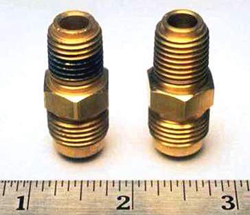 Figure 7 Of course, stress analyses should always be performed for heavily loaded, pressure-retaining or safety-related products. But even here, direct substitution of Free-Cutting Brass for leaded steel is usually possible. For example,Figure 7 shows a pneumatic hose fitting for a truck brake system. Made from alloy C36000, it is a direct replacement for a fitting formerly made from 12L14 steel. The only differences are that the brass fitting doesn't require electroplating and that it costs less than the same part made from steel.
Machinability
The most important feature of C36000 is, of course, its unexcelled machinability. No material of comparable strength machines faster and produces better surface finishes than Free-Cutting Brass. Brass's two-phase structure tends to form broken chips instead of continuous coils, which would interfere with high speed machining. Lead acts synergistically with the alpha-beta structure, causing chips to shatter into tiny fragments. Lead also provides some internal lubrication against the surface of the cutting tool.
Maximum recommended form-tool and single-point cutting speeds for Free-Cutting Brass are between 300 and 1,000 sfm (surface feet per minute) with high speed steel tooling and between 500 and 1,600 sfm with carbide. Corresponding maximum speeds for leaded steel range between 200 and 300 sfm (about 10% higher in proprietary resulfurized, rephosphorized, tellurium- or selenium-treated grades). Screw-machine operators tend not to run their equipment at maximum speed for either brass or steel and therefore don't take full advantage of brass's high-speed capability, but the difference between these "handbook" machinabilities for brass and steel shows what could be accomplished, if pursued. In fact, Free-Cutting Brass's machinability far surpasses the speed capacities of today's fastest commercial machine tools. Major breakthroughs are still a few years into the future, but ultra-high speed machining at up to 18,000 sfm (5,500 meters per minute) has already been demonstrated on a pilot scale in Europe.
Brass's high machinability also means measurably better surface finishes than can be achieved with leaded steel, even at brass's faster cutting speeds and higher feed rates. Dimensional control is simpler with Free-Cutting Brass because of substantially reduced tool wear. Fewer out-of-tolerance parts mean lower rejection rates and lower net production costs.
| Material Designation |
Corresponding Material Symbol |
| GB/T8890 |
ASTM B111 |
BS2871 |
JIS H3300 |
DIN 1785 |
| Copper-Nickel |
BFe10-1-1 |
C70600 Pipe |
CN102 |
C7060 |
CuNi10Fe1Mn |
| BFe30-1-1 |
C71500 Pipe |
CN107 |
C7150 |
CuNi30Mn1Fe |
| (BFe30-2-2) |
C71640 |
CN108 |
C7164 |
CuNi30Fe2Mn2 |
| (BFe5-1.5-0.5) |
C70400 |
– |
– |
– |
| B7 |
– |
– |
– |
– |
| Aluminium Brass |
HAL77-2 |
C68700 Tube |
CZ110 |
C6870 |
CuZn20Al2 |
| Admiralty Brass |
HSn70-1 |
C44300 Tube |
CZ111 |
C4430 |
CuZn28Sn1 |
| Boric Brass |
Hsn70-18 |
– |
– |
– |
– |
| HSn70-1 AB |
– |
– |
– |
– |
| Arsenical Brass |
H68A |
– |
CZ126 |
– |
– |
| Brass Tubes |
H65/H63 |
C28000/C27200 |
CZ108 |
C2800/C2700 |
CuZn36/CuZn37 |
ASTM B111 is issued under the fixed designation B111/B111M; the number immediately following the designation indicates the year of original adoption or, in the case of revision, the year of last revision. A number in parentheses indicates the year of last reapproval.
C70600 . . . 90-10 Copper-Nickel
This specification establishes the requirements for C70620 ... 90-10 Copper-Nickel— Welding Grade
seamless tube and ferrule stock of copper and various copper alloys up to 31⁄8 in. [80 mm] inclusive, in diameter, for use in C71000 . . . 80-20 Copper-Nickel C71500 . . . 70-30 Copper-Nickel
surface condensers, evaporators, and heat exchangers. The following coppers and copper alloys are specified:3 (Warn- ing—Mercury is a definite health hazard in use and disposal. C71520 C71640 70-30 Copper-Nickel—
Welding Grade Copper-nickel-iron- manganese (See 12.1.))
C10100 C10200 | OFE | Oxygen-free electronic Oxygen-free without | | OFA | residual deoxidants | C10300 | | Oxygen-free, extra low | | ... | phosphorus | C10800 | | Oxygen-free, low | | rrr ... | phosphorus | C12000 |
DLPA | Phosphorized, low residual phosphorus | C12200 |
DHPA | Phosphorized, high residual phosphorus | C14200 | DPAA | Phosphorized, arsenical | C19200 | . . . | Phosphorized, 1 % iron | C23000 | . . . | Red Brass | C28000 | . . . | Muntz Metal | C44300 Tube | | Admiralty Metals, B, C, | | ... | and D | C44400 | | | C44500 | | | C60800 | . . . | Aluminum Bronze | C61300 | . . . | . . . | C61400 | . . . | Aluminum Bronze, D | C68700 Tube | . . . | Aluminum Brass, B | C70400 | . . . | 95-5 Copper-Nickel |
C10100 C10200 | OFE | Oxygen-free electronic Oxygen-free without | | OFA | residual deoxidants | C10300 | | Oxygen-free, extra low | | ... | phosphorus | C10800 | | Oxygen-free, low | | ... | phosphorus | C12000 |
DLPA | Phosphorized, low residual phosphorus | C12200 |
DHPA | Phosphorized, high residual phosphorus | C14200 | DPAA | Phosphorized, arsenical | C19200 | . . . | Phosphorized, 1 % iron | C23000 | . . . | Red Brass | C28000 | . . . | Muntz Metal | C44300 | | Admiralty Metals, B, C, | | ... | and D | C44400 | | | C44500 | | | C60800 | . . . | Aluminum Bronze | C61300 | . . . | . . . | C61400 | . . . | Aluminum Bronze, D | C68700 | . . . | Aluminum Brass, B | C70400 | . . . | 95-5 Copper-Nickel | Copper or Copper Alloy UNS No. Previously Used Designation Description C72200 . . . . . . A Designations listed in Classification B224. Units—The values stated in either SI units or inch- pound units are to be regarded separately as standard. The values stated in each system may not be exact equivalents; therefore, each system shall be used independently of the other. Combining values from the two systems may result in non- conformance with the standard. The following safety hazards caveat pertains only to the test methods portion, Section 19, of this specification: This standard does not purport to address all of the safety concerns, if any, associated with its use. It is the responsibility of the user of this standard to establish appropriate safety and health practices and determine the applicability of regulatory limita- tions prior to use. Referenced DocumentsThe following documents in the current issue of the Annual Book of ASTM Standards form a part of this specifi- cation to the extent referenced herein: ASTM Standards:4 B153 Test Method for Expansion (Pin Test) of Copper and Copper Alloy Pipe and Tubing
B154 Test Method for Mercurous Nitrate Test for Copper Alloys B170 Specification for Oxygen-Free Electrolytic Copper— Refinery Shapes B224 Classification of Coppers B846 Terminology for Copper and Copper Alloys B858 Test Method for Ammonia Vapor Test for Determining Susceptibility to Stress Corrosion Cracking in Copper Alloys E8 Test Methods for Tension Testing of Metallic Materials E8M Test Methods for Tension Testing of Metallic Materials [Metric] (Withdrawn 2008)5 E29 Practice for Using Significant Digits in Test Data to Determine Conformance with Specifications E53 Test Method for Determination of Copper in Unalloyed Copper by Gravimetry E54 Test Methods for Chemical Analysis of Special Brasses and Bronzes (Withdrawn 2002)5 E62 Test Methods for Chemical Analysis of Copper and Copper Alloys (Photometric Methods) (Withdrawn 2010)5 E75 Test Methods for Chemical Analysis of Copper-Nickel and Copper-Nickel-Zinc Alloys (Withdrawn 2010)5 E76 Test Methods for Chemical Analysis of Nickel-Copper Alloys (Withdrawn 2003)5 E112 Test Methods for Determining Average Grain Size E243 Practice for Electromagnetic (Eddy Current) Examina- tion of Copper and Copper-Alloy Tubes E255 Practice for Sampling Copper and Copper Alloys for the Determination of Chemical Composition E478 Test Methods for Chemical Analysis of Copper Alloys E527 Practice for Numbering Metals and Alloys in the Unified Numbering System (UNS)
Terminology
Definitions:
For definitions of terms relating to copper and copper alloys, refer to Terminology B846.
Definitions of Terms Specific to This Standard:
capable of—the test need not be performed by the producer of the material. However, should subsequent testing by the purchaser establish that the material does not meet these requirements, the material shall be subject to rejection.
Ordering Information
Include the following information when placing orders for product under this specification:
ASTM Designation and year of approval (for example, ASTM B111/B111M – 04),
Copper or Copper Alloy UNS Designation (see Table 1),
Form (tube or ferrule stock),
Temper (see Temper section),
Dimensions, outside diameter, and wall thickness,
The following options are available and should be specified at the time of placing of the order when required:
Tension Test required per ASME Boiler and Pressure Vessel Code, Mechanical Properties section.
Pressure test as an alternative to eddy current test (Nondestructive Testing Section).
If the cut ends of the tubes do not need to be deburred (Workmanship, Finish, and Appearance section).
If the product is to be subsequently welded (Table 1, Footnotes G and H).
Residual Stress Test—Ammonia Vapor Test or Mer- curous Nitrate Test (Performance Requirements Section).
For Ammonia Vapor Test, risk level (pH value) if other than 10.
Heat identification or traceability details (Number of tests and Retests section).
Certification (Certification Section).
Mill Test Report (Mill Test Report Section).
If a subsequent thermal treatment after straightening is required (Temper section).
Materials and Manufacture
Materials—The material shall be of such quality and purity that the finished product shall have the properties and characteristics prescribed in this specification.
Manufacture—The product shall be produced by pro- cesses such as casting, extrusion, drawing, annealing, straightening, trimming, and other processes which may pro- duce a seamless tube in the specified condition.
Chemical Composition
The product shall conform to the chemical requirements specified in Table 1.
These composition limits do not preclude the presence of other elements. Limits for unnamed elements may be established by agreement between manufacturer or supplier and purchaser.
Copper Alloy UNS No. C19200—Copper may be taken as the difference between the sum of all the elements analyzed and 100 %. When all the elements in Table 1 are analyzed, their sum shall be 99.8 % minimum.
For copper alloys in which copper is specified as the remainder, copper may be taken as the difference between the sum of all the elements analyzed and 100 %.
When all the elements in Table 1 are analyzed, their sum shall be as shown in the following table:
whether minimum or nominal (Dimensions and Permissible Variations Section),
Quantity—total weight or total length or number of
Copper Alloy UNS No.
Copper Plus Named Elements, % min
pieces of each size, and
If product is purchased for agencies of the U.S. Government (see the Supplementary Requirements Section).
C60800 99.5
C61300 99.8
C61400 99.5
C70400 99.5
C70600 Pipe & C70620 99.5
C71000 99.5
C71500 & C71520 99.5
C71640 99.5
C72200 99.8
Copper or Copper
Nickel, TABLE 1 Chemical Requirements Composition, %
Other Alloy UNS No. CopperA Tin Aluminum incl Cobalt Lead, max Iron Zinc Manganese Arsenic Antimony Phosphorus Chromium Named Elements
A Copper (including silver).
max Ti.03
maxH
B This value is exclusive of silver and shall be determined by difference of “impurity total” from 100 %. “Impurity total” is defined as the sum of sulfur, silver, lead, tin, bismuth, arsenic, antimony, iron, nickel, mercury, zinc, phosphorus, selenium, tellurium, manganese, cadmium, and oxygen present in the sample.
C Impurity maximums in ppm for C10100 shall be: antimony 4, arsenic 5, bismuth 1, cadmium 1, iron 10, lead 5, manganese 0.5, mercury 1, nickel 10, oxygen 5, phosphorus 3, selenium 3, silver 25, sulfur 15, tellurium 2, tin 2, and zinc 1.
D Oxygen in C10200 shall be 10 ppm max. E Copper plus sum of named elements shall be 99.95 % min.
F Silicon shall be 0.10 % max. G When the product is for subsequent welding applications and is so specified by the purchaser, chromium shall be 0.05 % max, cadmium 0.05 % max, zinc 0.05 % max, and zirconium 0.05 % max. H When the product is for subsequent welding applications, and so specified by the purchaser, zinc shall be 0.50 % max, lead 0.02 % max, phosphorus 0.02 % max, sulfur 0.02 % max, and carbon 0.05 % max.
TABLE 2 Tensile Requirements—Inch-Pound Values
NOTE 1—See Table 3 for tensile requirements—SI values.
| Temper Designation | Tensile Strength, | Yield Strength,B Elongation | Copper or Copper Alloy UNS No. | Standard | Former | min ksiA | min ksiA | in 2 in., min % | C10100, C10200, C10300, C10800, C12000, C12200, | H55 | light-drawn | 36 | 30 | . . . | C14200 | | | | | | C10100, C10200, C10300, C10800, C12000, C12200, | H80 | hard-drawn | 45 | 40 | . . . | C14200 | | | | | | C19200 | H55 | light-drawn | 40 | 35 | . . . | C19200 | H80 | hard-drawn | 48 | 43 | . . . | C19200 | O61 | annealed | 38 | 12 | . . . | C23000 | O61 | annealed | 40 | 12 | . . . | C28000 | O61 | annealed | 50 | 20 | . . . | C44300, C44400, C44500 | O61 | annealed | 45 | 15 | . . . | C60800 | O61 | annealed | 50 | 19 | . . . | C61300, C61400 | O61 | annealed | 70 | 30 | . . . | C68700 | O61 | annealed | 50 | 18 | . . . | C70400 | O61 | annealed | 38 | 12 | . . . | C70400 | H55 | light-drawn | 40 | 30 | . . . | C70600, C70620 | O61 | annealed | 40 | 15 | . . . | C70600, C70620 | H55 | light-drawn | 45 | 35 | . . . | C71000 | O61 | annealed | 45 | 16 | . . . | C71500, C71520 | O61 | annealed | 52 | 18 | . . . | C71500, C71520 | | | | | | Wall thicknesses up to 0.048 in., incl | HR50 | drawn and stress-relieved | 72 | 50 | 12 | Wall thicknesses over 0.048 in. | HR50 | drawn and stress-relieved | 72 | 50 | 15 | C71640 | O61 | annealed | 63 | 25 | . . . | C71640 | HR50 | drawn and stress relieved | 81 | 58 | . . . | C72200 | O61 | annealed | 45 | 16 | . . . | C72200 | H55 | light-drawn | 50 | 45 | . . . | A ksi = 1000 psi. B At 0.5 % extension under load. | | | | | |
6.2.3 For copper alloys in which zinc is specified as the remainder, either copper or zinc may be taken as the difference between the sum of all the elements analyzed and 100 %.
6.2.3.1 When all the elements in Table 1 are analyzed, their sum shall be as shown in the following table:
Tubes of Copper Alloy UNS Nos. C10100, C10200, C10300, C10800, C12000, C12200, and C14200 shall be supplied in any one of the following tempers, one of which shall be specified: (1) light-drawn (H55), (2) hard-drawn (H80), or (3) hard drawn and end annealed (HE80). Copper Alloy UNS No. Copper Plus Named Elements, % min
Tubes of Copper Alloy UNS No. C19200 shall be supplied in any one of the following tempers, one of which
Temper
C23000 99.8
C28000 99.7
C44300 99.6
C44400 99.6 C44500 99.6 C68700 99.5
shall be specified: (1) annealed (O61), (2) light-drawn (H55), (3) hard-drawn (H80), or (4) hard-drawn, and end-annealed (HE80).
Tubes of Copper Alloy UNS Nos. C70400, C70600, C70620, and C72200 may be supplied in either light-drawn (H55) or annealed (O61) temper.
Tubes of Copper Alloy UNS Nos. C23000, C28000, C44300, C44400, C44500, C60800, C61300, C61400, C68700, and C71000 shall be furnished in the annealed (O61) temper unless otherwise specified on the purchase order.
Tubes of Copper Alloy UNS Nos. C71500, C71520, and C71640 shall be supplied in one of the following tempers as specified: (1) annealed (O61) or (2) drawn, and stress-relieved (HR50).
Tubes for ferrule stock shall be annealed sufficiently to be fully recrystallized.
Optional Post-Straightening Thermal Treatment—Some tubes, when subjected to aggressive environments, may have the potential for stress-corrosion cracking failure due to the residual stresses induced during straightening processing. For such applications, it is suggested that tubes of Copper Alloy UNS Nos. C23000, C28000, C44300, C44400, C44500,
TABLE 3 Tensile Requirements—SI Values NOTE 1—See Table 2 for tensile requirements—inch-pound values.
| Temper Designation | Tensile Strength, | Yield Strength,A Elongation | Copper or Copper Alloy UNS No. | Standard | Former | min MPa | min MPa | in 50 mm, min % | C10100, C10200, C10300, C10800, C12000, C12200, | H55 | light-drawn | 250 | 205 | . . . | C14200 | | | | | | C10100, C10200, C10300, C10800, C12000, C12200, | H80 | hard-drawn | 310 | 275 | . . . | C14200 | | | | | | C19200 | H55 | light-drawn | 275 | 240 | . . . | C19200 | H80 | hard-drawn | 330 | 295 | . . . | C19200 | O61 | annealed | 260 | 85 | . . . | C23000 | O61 | annealed | 275 | 85 | . . . | C28000 | O61 | annealed | 345 | 140 | . . . | C44300, C44400, C44500 | O61 | annealed | 310 | 105 | . . . | C60800 | O61 | annealed | 345 | 130 | . . . | C61300, C61400 | O61 | annealed | 480 | 205 | . . . | C68700 | O61 | annealed | 345 | 125 | . . . | C70400 | O61 | annealed | 260 | 85 | . . . | C70400 | H55 | light-drawn | 275 | 205 | . . . | C70600, C70620 | O61 | annealed | 275 | 105 | . . . | C70600, C70620 | H55 | light-drawn | 310 | 240 | . . . | C71000 | O61 | annealed | 310 | 110 | . . . | C71500, C71520 | O61 | annealed | 360 | 125 | . . . | C71500, C71520: | | | | | | Wall thicknesses up to 1.2 mm incl | HR50 | drawn and stress-relieved | 495 | 345 | 12 | Wall thicknesses over 1.2 mm. | HR50 | drawn and stress-relieved | 495 | 345 | 15 | C71640 | O61 | annealed | 435 | 170 | . . . | C71640 | HR50 | drawn and stress relieved | 560 | 400 | . . . | C72200 | O61 | annealed | 310 | 110 | . . . | C72200 | H55 | light-drawn | 345 | 310 | . . . | A At 0.5 % extension under load. | | | | | |
C60800, C61300, C61400, and C68700 be subjected to a stress-relieving thermal treatment subsequent to straightening. If required, this must be specified on the purchase order or contract. Tolerances for roundness and length, and the condi- tion of straightness, for tube so ordered, shall be to the requirements agreed upon between the manufacturer and the purchaser.
Mechanical Properties
Material specified to meet the requirements of the ASME Boiler and Pressure Vessel Code shall have tensile properties as prescribed in Table 2 or Table 3.
Grain Size for Annealed Tempers
Grain size shall be a standard requirement for all product in the annealed (O61) temper.
Samples of annealed-temper tubes selected for test shall be subjected to microscopical examination per Test Methods E112 at a magnification of 75 diameters and shall show uniform and complete recrystallization.
Products other than of Copper Alloy UNS Nos. C19200 and C28000 shall have an average grain size within the limits of 0.010 to 0.045 mm. These requirements do not apply to tubes of light-drawn (H55), hard-drawn (H80), hard-drawn and end-annealed (HE80), or drawn and stress-relieved tem- pers (HR50).
Expansion Test
Tube specimens selected for test shall withstand the expansion shown in Table 4 when expanded in accordance with
Test Method B153. The expanded tube shall show no cracking or rupture visible to the unaided eye.
Hard-drawn tubes not end annealed are not subject to this test. When tubes are specified end annealed, this test is required and shall be performed on the annealed ends of the sampled tubes.
Tubes for ferrule stock are not subject to the expansion test.
Flattening Test
Test Method—Each test specimen shall be flattened in a press at three (3) places along the length, each new place to be rotated on its axis approximately one third turn from the last flattened area. Each flattened area shall be at least 2 in. in length. A flattened test-specimen shall allow a micrometer caliper set at three (3) times the wall thickness to pass freely over the flattened area. The flattened areas of the test specimen shall be inspected for surface defects.
During inspection, the flattened areas of the test- specimen shall be free of defects, but blemishes of a nature that do not interfere with the intended application are acceptable.
Tubes for ferrule stock are not subject to flattening test.
Residual Stress Test
A residual stress test, when specified in the purchase order, is required only for Copper Alloy UNS Nos. C23000, C28000, C44300, C44400, C44500, C60800, C61300, C61400, and C68700 and when not supplied in an annealed temper.
| TABLE 4 Expansion Requirements | |
Standard | Temper Designation Copper or Copper Alloy UNS No. Former | Expansion of Tube Outside Diameter, in Percent of Original Outside Diameter | O61 | annealed C19200 | 30 | | C23000 | 20 | | C28000 | 15 | | C44300, C44400, C44500 | 20 | | C60800 | 20 | | C61300, C61400 | 20 | | C68700 | 20 | | C70400 | 30 | | C70600, C70620 | 30 | | C71000 | 30 | | C71500, C71520 | 30 | | C71640 | 30 | | C72200 | 30 | H55 | light-drawn C10100, C10200, C10300, C10800, | 20 | | C12000, C12200 | | | C14200 | 20 | | C19200 | 20 | | C70400 | 20 | | C70600, C70620 | 20 | |
C72200 | 20 | HR50 | drawn and stress relieved C71500, C71520 | 20 | | C71640 | 20 | . . . | hard-drawn and end annealed C10100, C10200, C10300, C10800, | 30 | | C12000, C12200, C14200 | |
Unless otherwise specified, the producer shall have the option of testing the product to either the mercurous nitrate test, Test Method B154, or the ammonia vapor test, Test Method B858, as prescribed below.
Mercurous Nitrate Test:
Warning—Mercury is a definite health hazard and therefore equipment for the detection and removal of mercury vapor produced in volatilization is recommended. The use of rubber gloves in testing is advisable.The test specimens, cut 6 in. [150 mm] in length, shall withstand without cracking, an immersion in the standard mercurous nitrate solution prescribed in Test Method B154. The test specimen shall include the finished tube end. - Ammonia Vapor Test:
-
The test specimens, cut 6 in. [150 mm] in length, shall withstand without cracking ,the ammonia vapor test as prescribed in Test Method B858. For the purposes of this specification, unless otherwise agreed between purchaser and supplier, the risk level identified in the Annex of Method B858, shall be specified as risk level (pH value) of 10.
Nondestructive Testing
Each tube shall be subjected to the eddy-current test in
13.1.1. Tubes may be tested in the final drawn, annealed, or heat-treated temper or in the drawn temper before the final anneal or heat treatment unless otherwise agreed upon by the supplier and the purchaser. The purchaser may specify either of the tests in 13.1.2 or 13.1.3 as an alternative to the eddy-current test.
Eddy-Current Test—Each tube shall be passed through an eddy-current testing unit adjusted to provide information on the suitability of the tube for the intended application. Testing shall follow the procedures of Practice E243.
The depth of the round-bottom transverse notches and the diameters of the drilled holes in the calibrating tube used to adjust the sensitivity of the test unit are shown in Tables 5 and 6, and Tables 7 and 8, respectively.
Tubes that do not actuate the signaling device of the eddy-current tester shall be considered to conform to the requirements of this test. Tubes causing irrelevant signals because of moisture, soil, and like effects may be reconditioned and retested. Such tubes, when retested to the original test parameters, shall be considered to conform if they do not cause output signals beyond the acceptable limits. Tubes causing irrelevant signals because of visible and identifiable handling marks may be retested by the hydrostatic test prescribed in 13.1.2, or the pneumatic test prescribed in 13.1.3. Tubes meeting requirements of either test shall be considered to conform if the tube dimensions are within the prescribed limits, unless otherwise agreed upon between the manufacturer and the purchaser.
Hydrostatic Test—Each tube shall stand, without showing evidence of leakage, an internal hydrostatic pressure sufficient to subject the material to a fiber stress of 7000 psi [48 MPa] as determined by the following equation for thin hollow cylinders under tension. The tube need not be tested at a hydrostatic pressure of over 1000 psi [7.0 MPa] unless so specified. P 5 2St/~D 2 0.8t!
where:
P = hydrostatic pressure, psig [MPa];
t = thickness of tube wall, in. [mm];
D = outside diameter of the tube, in. [mm]; and
S = allowable stress of the material, psi [MPa].
Pneumatic Test—Each tube shall be subjected to an internal air pressure of 60 psig [400 kPa], min, for 5 s without |