Speeds and Feeds for Drilling and Reaming Stainless Steel
Traditionally high speed tool steel have been used for drilling and reaming, but carbide tipped tools are also used for specialised jobs or long production runs.
Drilling
The work hardening effect when drilling the austenitic stainless steel grades eg 304, 316L is the main cause of problems. The steel hardens progressively as it is cold worked, but it also important to make sure that the steel is fully annealed (softened) when deep or small diameter holes are to be drilled. Cold drawn bar products should be avoided.
As with any machining operation, rigid machines and tooling should be used when drilling or reaming. Drilling jigs should be used, where possible, to help keep the work-piece rigid.
Centre punching with conventional conical shaped punches can result in enough localized work hardening to make drill entry difficult. This can make the drill tip deflect or wander, glaze the surface and/or blunt the drill tip and result in drill breakages, particularly where small diameter holes are being drilled. Where a punch mark is needed to help get the hole started, a light mark using a three-cornered pyramid tip punch is a better idea.
During drilling it is essential to maintain the feed to cut through the work hardened layer generated as the metal is cut. Dwell or rubbing must be avoided. Entry and re-entry after backing out should be done at full speed and feed rate.
It may be necessary to reduce tool speed to ensure that the feed rate can be maintained, without causing other problems. Drilling chips must be allowed to get away from the hole being drilled, freely. Any build up of chips in the hole can cause roughness of the hole-wall, or in cases of severe clogging, drill breakage. When deep holes are being drilled, the drill should be backed-out frequently with minimum dwell as follows:
| Drilling sequence |
Maximum drilling depth |
| 1st bite |
3-4 x drill dia. |
| 2nd bite |
2 x drill dia. |
| 3rd and subsequent bites |
1 x drill dia. |
When drilling through-holes a backing plate should be used to help avoid drill breakages as the drill comes out of the blind side of the hole.
Drill geometry
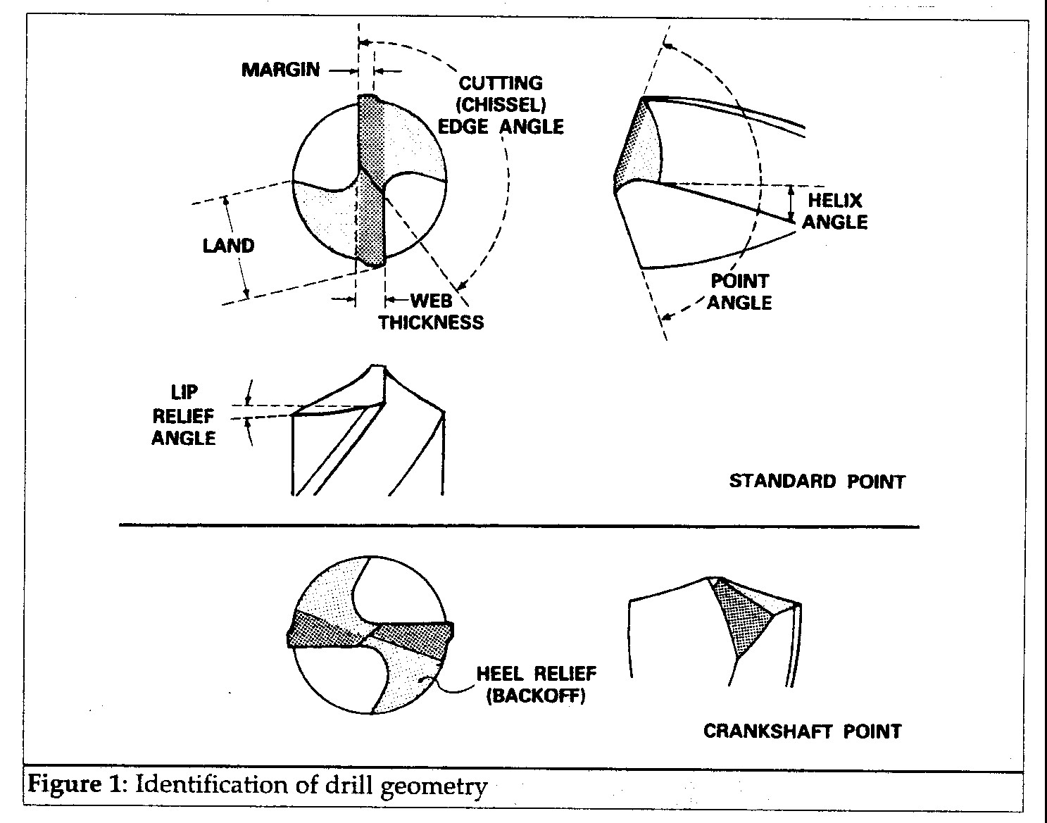
Although standard High Speed Steel drills are suitable for drilling stainless steel, they should preferably be shorter to reduce deflection and breakages in use. Carbide tipped drills can also be used. The web thickness should be around 1/8th of the drill diameter, except for small diameters where thicker webs improve the strength and rigidity of the drill shank. This can however impede chip flow. Conversely, with a thinner the web although the drill will have less rigidity, chip flow and removal should be easier and it is easier to get the drill to start the hole.
Normally the web thickness increases along the length of the drill (away from the point). When the drill tip is being reground, the exposed web should also be thinned to compensate for grinding back up the length of the drill.
The cutting angle should be around 135 degrees. Larger angles produce thinner chips that should be easier to remove, which is important when drilling stainless steel. Lower angles of around 120 can however be used for drilling free-machining grades (eg 303 1.4305). Wear to the drill point can indicate that a larger point angle should be used. Both cutting edges must be at the same angle to the centre line of the drill and be the same length. A mixture of chip sizes can indicate that that the two cutting edge angles and lengths are not the same.
Lip relief angles decrease as the drill diameter increases and suggested angles are:
3mm - 16 degrees
6mm - 14 degrees
12mm - 12 degrees
20mm - 10 degrees
25mm - 8 degrees
Excessive feed pressure, poor cutting with sharp drills or drill breakages can indicate that the drill tip has an insufficient lip relief angle. Conversely, if the drill is tending to dig-in then a reduced lip angle may be better. In any event, it is essential that drills are sharp and properly ground.
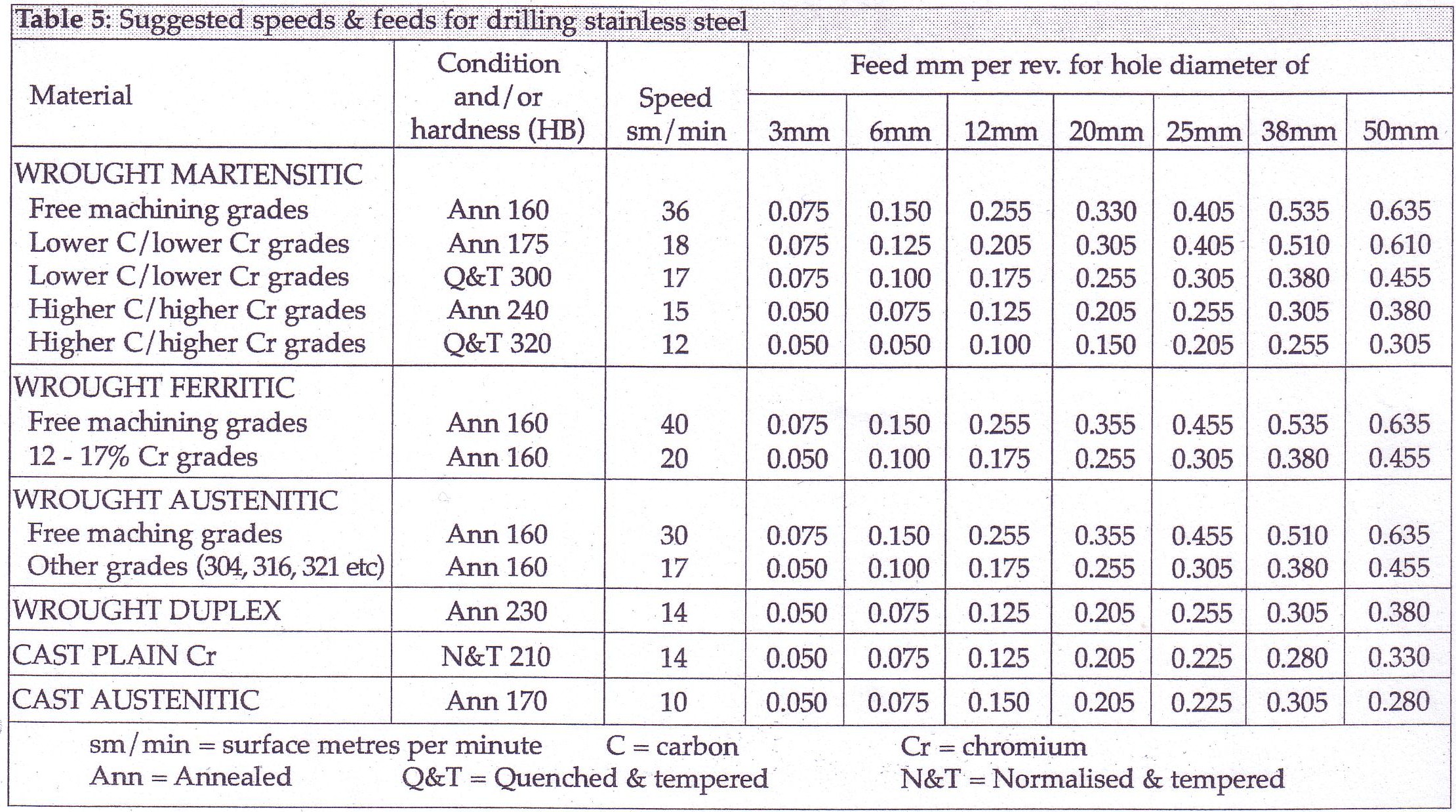
Feeds and Speeds
Both too slow and too fast drill speeds can cause drill breakages. It is important that small diameter drills are not used at too slow a speed. Excessive speed however is a major cause of drill breakages. Drilling machines with continuous speed change control are better than stepped or discrete speed change gear boxes for drilling stainless steel. When drilling deep holes, reduce the speed and feed as the drill moves into the metal. With depths up to 3 times the hole diameter, no reduction is necessary, but with deeper holes, the speed and feed should be reduced as follows:
| Depth |
Speed |
Feed |
| Up to 3 x diameter |
normal |
normal |
| 3 x diameter |
-10% |
-10 |
| 4 x diameter |
-20 % |
-10% |
| 5 x diameter |
-30% |
-20% |
| 6 x diameter |
-35% |
-20% |
A rough hole wall can result if too high a feed rate is used. If this happens, reduce feed and increase speed.
Reaming
Cold working during drilling, punching or machining the preparation hole prior to reaming austenitic stainless steel must be minimised. Sufficient material must be left on the hole wall however to allow a positive reaming cut to be made to undercut the new work-hardened layer produced.
Reamer geometry

Spiral fluted reamers are preferable for working with stainless steel as they produce less chatter and help the flow of chips better than straight fluted tools.
For normal clockwise tool rotation, right hand spiral tools cut more freely than left hand spiral tools, but tend to self-feed into the hole. Left hand (reverse) spiral tools have a lower tendency to self-feed which can be beneficial when precise feed rate control is needed.
The rake angles should be between 3 and 8 degrees, larger angles suiting austenitic stainless steel grades (304, 1.4301 316, 1.4401 etc). Margin widths should be 0.125-0.35 mm for HSS tools and 0.05-0.125 mm for carbide tool. The margin width should increase, within these ranges for larger tool diameters.
The preferred tool angles (degrees) are summarised as follows:
| Primary relief angle |
4-6 (HSS) 6-12 (carbide) |
| Chamfer angle |
30-35 |
| Chamfer relief angle |
4-5 |
| Helix angle |
7 |
| Lead angle |
2 (carbide tools only) |
Insufficient primary relief or too wide a land can cause tool chatter
Feeds and Speeds
To improve the surface finish of the finally reamed hole, the speeds suggested can be reduced by 50%. Rough finished machined surfaces or dulling or burning of the cutting edges usually indicate that the speed is too high.

Related References:
Screw Thread Limits Table
UNC UNF Threads Per Inch TPI Threads Per Inch
Wood Screw Pilot Hole Sizes Table
Standard NPT National Pipe Thread Tap Drill Sizes Table
ASTM ISO Metric Thread Sizes and Tap Drill Table
Tapping Drill Size and Clearance Drill Size for Metric Threads
Standard Number Drill Sizes Table
Metric Thread Size Tap Drill Table
Standard Tap Drills Clearance Holes Table
Standard Letter Drill Sizes Table
Standard Drill Sizes Decimal Equivalents Table
Socket Head Cap Screw Sizes Dimension Table
SAE Grade ASTM Bolt Identify Marks Mechanical Properties
Steel Bolt Torque Specifications Table
Finished Hex Nut Dimensions
Heavy Hex Nut Dimensions Table
Standard ANSI Type B Flat Washer Sizes
Circumferential Speeds for High Speed Twist Drill Table
|