Large Steam System Condensers
Stainless Steel Condenser Tube
The steam condenser, shown in Figure 9 below, is a major component of the steam cycle in power generation facilities. It is a closed space into which the steam exits the turbine and is forced to give up its latent heat of vaporization. It is a necessary component of the steam cycle for two reasons. One, it converts the used steam back into water for return to the steam generator or boiler as feedwater. This lowers the operational cost of the plant by allowing the cleaning and treated condensate to be reused, and it is far easier to pump a liquid than steam. Two, it increases the cycle's efficiency by allowing the cycle to operate with the largest possible delta- T and delta-P between the source (boiler) and the heat sink (condenser).
Because condensation is taking place, the term latent heat of condensation is used instead of latent heat of vaporization. The steam's latent heat of condensation is passed to the water flowing through the tubes of the condenser.
After the steam condenses, the saturated liquid continues to transfer heat to the cooling water as it falls to the bottom of the condenser, or hotwell. This is called subcooling, and a certain amount is desirable. A few degrees subcooling prevents condensate pump cavitation. The difference between the saturation temperature for the existing condenser vacuum and the temperature of the condensate is termed condensate depression. This is expressed as a number of degrees condensate depression or degrees subcooled. Excessive condensate depression decreases the operating efficiency of the plant because the subcooled condensate must be reheated in the boiler, which in turn requires more heat from the reactor, fossil fuel, or other heat source.
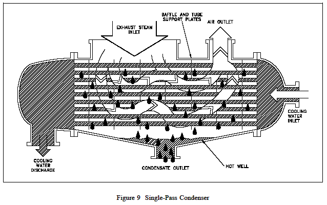
There are different condenser designs, but the most common, at least in the large power generation facilities, is the straight-through, single-pass condenser illustrated Figure 9 above. This condenser design provides cooling water flow through straight tubes from the inlet water box on one end, to the outlet water box on the other end. The cooling water flows once through the condenser and is termed a single pass. The separation between the water box areas and the steam condensing area is accomplished by a tube sheet to which the cooling water tubes are attached. The cooling water tubes are supported within the condenser by the tube support sheets. Condensers normally have a series of baffles that redirect the steam to minimize direct impingement on the cooling water tubes. The bottom area of the condenser is the hotwell. This is where the condensate collects and the condensate pump takes its suction. If noncondensable gasses are allowed to build up in the condenser, vacuum will decrease and the saturation temperature at which the steam will condense increases.
Non-condensable gasses also blanket the tube of the condenser, thus reducing the heat transfer surface area of the condenser. This surface area can also be reduced if the condensate level is allowed to rise over the lower tubes of the condenser. A reduction in the heat transfer surface has the same effect as a reduction in cooling water flow. If the condenser is operating near its design capacity, a reduction in the effective surface area results in difficulty maintaining condenser vacuum.
The temperature and flow rate of the cooling water through the condenser controls the temperature of the condensate. This in turn controls the saturation pressure (vacuum) of the condenser. To prevent the condensate level from rising to the lower tubes of the condenser, a hotwell level control system may be employed. Varying the flow of the condensate pumps is one method used to accomplish hotwell level control. A level sensing network controls the condensate pump speed or pump discharge flow control valve position. Another method employs an overflow system that spills water from the hotwell when a high level is reached.
Condenser vacuum should be maintained as close to 29 inches Hg as practical. This allows maximum expansion of the steam, and therefore, the maximum work. If the condenser were perfectly air-tight (no air or noncondensable gasses present in the exhaust steam), it would be necessary only to condense the steam and remove the condensate to create and maintain a vacuum. The sudden reduction in steam volume, as it condenses, would maintain the vacuum. Pumping the water from the condenser as fast as it is formed would maintain the vacuum. It is, however, impossible to prevent the entrance of air and other noncondensable gasses into the condenser. In addition, some method must exist to initially cause a vacuum to exist in the condenser. This necessitates the use of an air ejector or vacuum pump to establish and help maintain condenser vacuum.
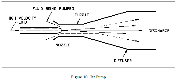
Air ejectors are essentially jet pumps or eductors, as illustrated in Figure 10 below. In operation, the jet pump has two types of fluids. They are the high pressure fluid that flows through the nozzle, and the fluid being pumped which flows around the nozzle into the throat of the diffuser. The high velocity fluid enters the diffuser where its molecules strike other molecules. These molecules are in turn carried along with the high velocity fluid out of the diffuser creating a low pressure area around the mouth of the nozzle. This process is called entrainment. The lowpressure area will draw more fluid from around the nozzle into the throat of the diffuser. As the fluid moves down the diffuser, the increasing area converts the velocity back to pressure. Use of steam at a pressure between 200 psi and 300 psi as the high pressure fluid enables a singlestage air ejector to draw a vacuum of about 26 inches Hg.
Normally, air ejectors consist of two suction stages. The first stage suction is located on top of the condenser, while the second stage suction comes from the diffuser of the first stage. The exhaust steam from the second stage must be condensed. This is normally accomplished by an air ejector condenser that is cooled by condensate. The air ejector condenser also preheats the condensate returning to the boiler. Two-stage air ejectors are capable of drawing vacuums to 29 inches Hg.
A vacuum pump may be any type of motor-driven air compressor. Its suction is attached to the condenser, and it discharges to the atmosphere. A common type uses rotating vanes in an elliptical housing. Single-stage, rotary-vane units are used for vacuums to 28 inches Hg. Two stage units can draw vacuums to 29.7 inches Hg. The vacuum pump has an advantage over the air ejector in that it requires no source of steam for its operation. They are normally used as the initial source of vacuum for condenser start-up.
|