Selecting an Liquid-to-Liquid Cooling System
Selecting a Cooling System: Ambient Cooling System | Recirculating Chiller | Liquid-to-Liquid Cooling System | Recirculating Chiller or Liquid-to-Liquid Cooling System | Selecting A Cold Plate Technology | Selecting A Pump | Selecting a Recirculating Chiller | Selecting A Modular Cooling System | Selecting an Liquid-to-Liquid Cooling System
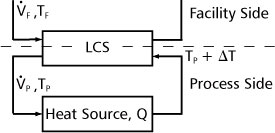
In most Liquid-to-Liquid Cooling System LCS™ sizing applications, we know the temperature of the facility water (TF), the desired process set-point temperature (TP), the flow rate through the process ( P) and the heat load of the process, Q. P) and the heat load of the process, Q.

To determine the required capacity, Q/ITD, we first need to calculate the change in temperature, ΔT, through the process. We can do this either by solving the heat capacity equation:

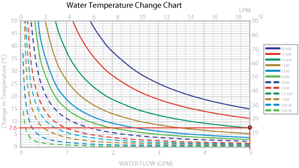
or by using the heat capacity graphs.
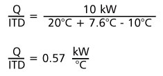
Next, we calculate Q/ITD to find the required cooling capacity. Q is the process heat load. ITD, the initial temperature difference, is the difference in temperature between the warm return water, (TP+ ΔT) and the cold facility water (TF).
So,

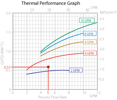
Finally, refer to the LCS performance curves to determine the facility process flow rate required to achieve the calculated Q/ITD.
Example:
A solder reflow oven requires a process set point of 20 °C. The heat load is 10 kW and the process water flow rate is 5 gpm. The facility water is at 10°C.
Using the heat capacity graphs, we find that the ΔT through the process is approximately 7.6°C for the condition 10 kW at 5 gpm.
We can now solve for Q/ITD as follows:

Referencing the LCS performance graph, we can see that a facility flow rate above 2 gpm will meet the required performance.


|
