Oxidation Behavior of Type 321 Stainless Steel Tube
Type 321 1.4541 is an austenitic chromium-nickel stainless steel containing titanium, applied extensively to the equipment without the risk of intergranular corrosion at the temperature between 430°C and 870°C such as pressure tanks, heat exchanger, etc.
However, severe oxidation occurred to the 321 stainless steel tube in a heat changer at the temperature about 700°C. The stainless steel tube began to peel off after two-month service.
In order to find out the reason for oxidation, the scaled tubes were investigated, and simulation experiments were carried out on the unused and same kind of 321 stainless steel. The experiments show that the coexistence of α and γ phases in the austenitic steel mainly accounts for the invalidation of the stainless steel tube.
Experimental
Firstly, the scaling tube cut from the heat exchanger are investigated, and then, the unused 321 stainless steel tube with the same specification is cut into the specimens of 25mm 10mm and are put into hot air furnaces at 700 °C and 900 °C, respectively. Before the experiment, the tube was washed carefully, and the oxidation samples are taken out every certain isothermal time.
The mass gain due to oxidation is measured using a balance with a precision of 0.1 mg. The phase components are characterized by an X-ray diffractometer (XRD) using Cu Kα radiation. Scanning electron microscopy (SEM) and electron probe micro-analyzer (EPMA) are employed to investigate the surface morphology and the cross-section of the scale formed on the alloy.
3 Results
3.1 Tube from the heat exchanger
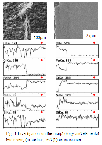 Fig. 1a shows the surface morphology of the specimen and the elemental line scans across two different parts. The right side is smooth, with rich Fe and poor Cr, Si and Ni; while the condition on the left side is just opposite. The surface is much rough, Fe is poor, and Cr, Si and Ni rich. Fig. 1a shows the surface morphology of the specimen and the elemental line scans across two different parts. The right side is smooth, with rich Fe and poor Cr, Si and Ni; while the condition on the left side is just opposite. The surface is much rough, Fe is poor, and Cr, Si and Ni rich.
Fig. 1b shows the cross-sectional micrograph and elemental line scans the oxide scale. The scale is composed of two layers. The outer layer partly peels off (the outmost left side), which is mainly Fe oxide, and also contains a minor amount of Ni and Si. The inner layer contains rich Cr and Ni, poor Fe, indicating the enrichment of Cr and Ni elements. According to Fig. 1b, it can be deduced that a piece of oxidation scale in the rough, left side, as shown in Fig. 1a, has peeled off.
3.2 Experiment at 700 °C
Fig. 2 shows the mass gain of the specimens under isothermal exposure at different time. In this figure, a typical oxidation kinetics curve of stainless steel is also presented [1]. Because the oxide scales peel off, the measurement result severely deviates from the parabolic law. The results here show an evidence of the extent of scaling.
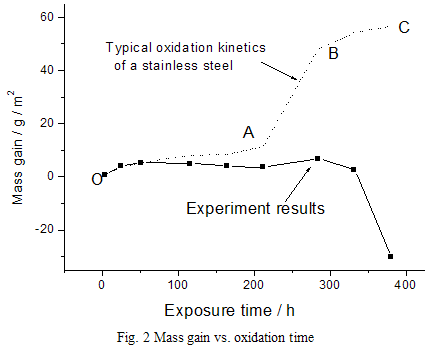
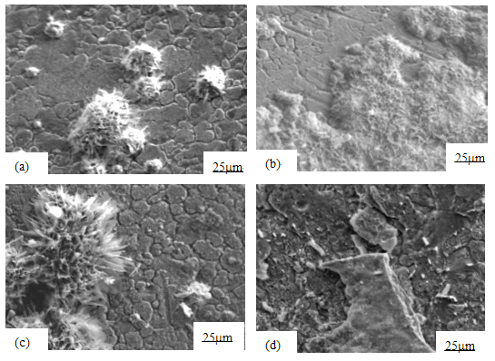
Fig. 3 shows the surface morphology after oxidation, illustrating a common characteristic of the cactus-like oxides. The oxides nucleate and grow (Fig. 3a, 4h), then congregate to a swarm when oxidation continues (Fig. 3b, 51h). With further oxidation, the swarm of "cacti" disappears, but some big"cacti" scatter over the observed surface (Fig. 3c, 212h). The scale obviously peels off after isothermal exposure for 380 h (Fig. 3d), showing a similar morphology to Fig 1a.
The XRD profiles are represented in Fig. 4. The oxide on the specimen from the exchanger is mainly Fe2O3. In our simulation experiments, the oxide formed on the specimen is similar to that from the heat exchanger. Further more, with the elongation of exposure time, the peaks of γ phase become gradually shorter while that of α phase higher and higher. That is to say, the phase content is changing. The α phase content increases while γ phase disappears with oxidation time extending.
According to the oxide identified by XRD (Fig. 4) and the elemental distribution characteristics (Fig. 1b), it can be deduced that two-layer structured film (outer layer is Fe2O3, and inner layer is FeCr2O4 and NiCr2O4 ) forms on the surface of the tube, either in the heat exchanger or in the 700 °C experiment after a long time exposure. The two layer structure is closely associated with the abrupt increase in mass gain (curve AB in Fig. 2) [1], and prone to spall off, which is supported by our measurement results: the curve deviation from the right kinetics is owing to the scale spallation.
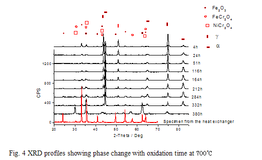
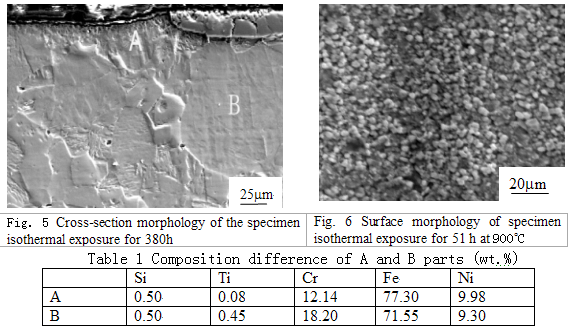
Fig.5 shows the cross-section morphology. When the specimen is slightly etched by a solution (HCl: HNO3 = 1:3), The scale in part A peels off , but still exists in part B. The compositions in the two parts are different, shown in Table 1. The Cr content in part A decreases to 12.14 %, much lower than the original level.
3.3 Experiment at 900 °C
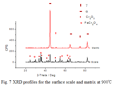
The specimen presents austenitic state at temperature of 900 °C. Therefore, the oxidation appears at a single austenitic state. Fig. 6 shows the surface morphology of specimen with an oxidation time of 51h. It can be seen that very even and compact scale forms.
The constituent phases of the surface scale are Cr2O3 and FeCr2O4, but Fe2O3 is not detected (Fig. 7). This kind of scale hardly peels off. After the scale being wiped off, a mixture phase of α and γ is identified by XRD. It can be deduced that when the specimens are cooled to room temperature, phase transformation takes place. Therefore, both α and γ phases coexist at room temperature.
4 Discussions
When the stainless steel is exposed to oxygen, an oxide film forms on the surface. At low temperature, the film is thin, but at high temperature, the oxide thickness increases continuously when time goes on. The excellent anti-oxidation capability of stainless steel is associated with the formation of Cr2O3 scale. That is because the diffusion of ions across the Cr2O3 scale is very slow, and then the growth rate of the scale is significantly decreased [2,3].
Why does the protective scale not form on the surface of the experimented stainless steel? Usually, 321 stainless steel should be supplied in solution treated state according to the ASTM standard. Experiment shows that α and γ phases coexist in this steel tube. How does ferrite in austenitic steel influence alloy steel?
4.1 Elements redistribution
It is known that the element content is different in different phases; the coexistence of α and γ phases would induce the process of the elements redistribution. The contents of chromium and silicon are higher while carbon and nickel lower in α phase, compared to that in γ phase [1].
Type 321 stainless steel is sensitive at the service temperature of 700 °C, and M(Fe,Cr)23C6 may form on the phase boundary, although the alloy is stabilized through adding TiC to decrease the carbon content. Owing to the redistribution of alloying elements, the Cr content of γ phase decreases. The relatively higher carbon content for γ phase makes the precipitation of carbide possible in a long isothermal exposure. Chromium in M23C6 mainly comes from α phase, while carbon from γ phase, which results in the poor Cr region in the α side, and then an overall decrease of the chromium content in a certain area of matrix. Moreover, the phase boundary of the two coexisting phases, provides a passage for ions transporting from inner matrix to the oxide / matrix interface, as well as a preferential nucleation site of the precipitation of carbide.
Because the sensitivity of chromium is high, at the initial stage of oxidation, the Cr2O3 forms on the surface of the tube, and then the Cr- poor region begins to form. Because the diffusion rate of chromium in α phase is higher than that in γ phase, the oxidation condition of different phase is not the same. As to the α phase, in the Cr-poor region, chromium content can be recovered rapidly, and the subsequent oxide can still be Cr2O3; but to γ phase, the oxide of matrix (FeCr2O4, NiCr2O4) may form because of the insufficient supply of chromium and the enrichment of Ni under the scale. The oxidation is severest in the Cr-poor site, especially near the phase boundary. The redistribution of Ni and Si contents in the two coexistent phases may also weaken the effect of the original design purpose. The enrichment of Ni and Si in the inner scale is founded in Fig. 1. The addition of Ni does not effectively provent the outer Cr2O3 scale transforming into the two-layer structure (outer Fe2O3, inner FeCr2O4 and NiCr2O4), and the oxide is not stabilized by addition Si. The Fe cations move outward to the surface scale to form Fe2O3, and then the easy scaling structure, the outer Fe2O3, inner FeCr2O4 and NiCr2O4, appears. Therefore, it can be concluded that the coexistence of α and γ phases in the should-be austenitic 321steel creates an important situation for the formation of the two-layer structure.
In all, the coexistence of α and γ phases in 321 steel greatly deteriorates the oxidation resistance at elevated temperature.
The experiment at 900 °C is scheduled to eliminate the possible side effects of the coexistent phases. Experimental results show that Cr2O3, not Fe2O3 forms on the specimens' surface. At this temperature, ions diffusion rate will increase significantly, and in the Cr-poor region, chromium content can be regained in a short time. The scale is compact, adhesive and not easy to spall off, showing an ideal anti-oxidation capability at high temperature. This experiment proves that the coexistent α and γ phases are harmful to oxidation resistance.
Although the scale spallation mainly results from the formation of the two-layer scale structure, other factors still promote the scale peeling off process.
4.2 Thermal expansion and wind force
As the experiment result shows, the phase content changes with the elongation of exposure time. It is known that the thermal expansion capability of γ phase is much higher than that of α phase. The changes of phase content, especially the decrease of γ content, will produce a tensile effect upon the outer scale. In the heating or cooling process in the heat exchanger, the matrix will also produce tensile or compressive effects on the scale correspondingly, because of the different thermal expansion capability of scale with matrix. The produced stress leads to the scale crack, as shown in Fig. 3. The cracks cause the metal exposure to oxygen, making the oxidation rate accelerate.
In the heat exchanger, the wind force of hot air acts on the surface oxide scale of the steel tube. Undoubtedly, the frictional force is beneficial to the scale spallation.
5 Conclusions
1) The two-layer structure scale, outer Fe2O3, inner FeCr2O4 and NiCr2O4, appears on the surface of a duplex Type 321 stainless steel in 700 °C hot air. The scale spalls off either in a heat exchanger or in the experiment furnace. When an experiment is carried out at 900 °C, in which the specimens are in austenitic state, the protective Cr2O3 scale forms.
2) The coexistence of α and γ phases results in the redistribution of the alloying elements, provides favorable nucleation sites, thus decreases the Cr content of the matrix, and therefore stimulates the formation of the two-layer structure. Therefore, the coexistence of α and γ phases, the wind force of hot air, the thermal expansion capability of different phases, together contribute to the scale spallation at 700C.
Reference
- Zhengjiao Wang, Youling Wu. Stainless Steel, Beijing: Chemical Industry Press, 1991
- Caplan D, Cohen M, High temperature oxidation of chromium-Nickel steel, Corrosion-National Association of Corrosion Engineers, 15:57-62, 1959
- Hales R, The high temperature oxidation behavior of austenitic stainless steels, Werkstoffe und Korrosion, 29:393-399
Related References:
Oxidation Resistance of Stainless Steel
Oxidation Behavior of Type 321 Stainless Steel Tube
310S Elevated Temperature Oxidation Resistance
316L Oxidation Resistance
317L Oxidation Resistance
321 Elevated Temperature Oxidation Resistance
347 Elevated Temperature Oxidation Resistance
410S Oxidation Resistance
|
