Yield Strength of Stainless Steel
The stress a material can withstand without permanent deformation. This is not a sharply defined point. Yield strength is the stress which will cause a permanent deformation of 0.2% of the original dimension. Point at which material exceeds the elastic limit and will not return to its origin shape or length if the stress is removed. This value is determined by evaluating a stress-strain diagram produced during a tensile strength test.
A value called "yield strength" of a material is defined as the stress applied to the material at which plastics deformation starts to occur while the material is loaded.
Yield strength is an important indictor for the most engineering design, which is influenced by many factors such as raw material quality, chemical composition, forming process, heat treatment process, etc. This article presents an example indicating the effect of heat treatment on yield strength of AISI 4140 alloy steel.
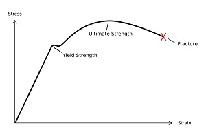
Yield strength is the amount of stress at which plastic deformation becomes noticeable and significant. Fig.1 is an engineering stress-strain diagram in tensile strength test. Because there is no definite point on the curve where elastic strain ends and plastic strain begins, the yield strength is chosen to be that strength when a definite amount of plastic strain has occurred. For the genera structural design, the yield strength is chosen when 0,2 percent plastic strain has taken place. The 0.2% yield strength or the 0.2% offset yield strength is calculated at 0.2% offset from the original cross-sectional area of the sample.
During yielding stage, the material deforms without an increase in applied load, but during the strain hardening stage, the material undergoes changes in its atomic and crystalline structure, resulting in increased resistance of material to further deformation.
Yield strength is a very important value for use in engineering structural design. If we are designing a component that must support a force during use, we must be sure that the component does not plastically deform. We must therefore select a material that has high yield strength, or we must make the component large enough so that the applied force produces a stress that is below the yield strength. In contrast, the tensile strength is relatively unimportant for ductile materials selection and application since too much plastics deformation takes place before it is reached. However, the tensile strength can give some indication of the materials, such as hardness and material defects.
Yield Strength of Stainless Steel according to ASTM A213
| Grade |
UNS Designation |
Tensile Strength, Min ksi [MPa] |
Yield strength, min ksi [MPa] |
Elongation in 2 in. or 50 mm, min, %A, B |
Hardness, Max Brinell/Vickers |
Hardness, Max Rockwell |
| TP304 |
S30400 |
75 [515] |
30 [205] |
35 |
192HBW/200Hv |
90HB |
| TP304L |
S30403 |
70 [485] |
25 [170] |
35 |
192HBW/200Hv |
90HB |
| TP304H |
S30409 |
75 [515] |
30 [205] |
35 |
192HBW/200Hv |
90HB |
| TP304N |
S30415 |
80 [550] |
35 [240] |
35 |
192HBW/200Hv |
90HB |
| TP310S |
S31008 |
75 [515] |
30 [205] |
35 |
192HBW/200Hv |
90HB |
| TP310H |
S31009 |
75 [515] |
30 [205] |
35 |
192HBW/200Hv |
90HB |
| TP316 |
S31600 |
75 [515] |
30 [205] |
35 |
192HBW/200Hv |
90HB |
| TP316L |
S31603 |
70 [485] |
25 [170] |
35 |
192HBW/200Hv |
90HB |
| TP316H |
S31609 |
75 [515] |
30 [205] |
35 |
192HBW/200Hv |
90HB |
| TP316Ti |
S31635 |
75 [515] |
30 [205] |
35 |
192HBW/200Hv |
90HB |
| TP317 |
S31700 |
75 [515] |
30 [205] |
34 |
192HBW/200Hv |
90HB |
| TP317L |
S31703 |
75 [515] |
30 [205] |
35 |
192HBW/200Hv |
90HB |
| TP321 |
S32100 |
75 [515] |
30 [205] |
35 |
192HBW/200Hv |
90HB |
| TP321H |
S32109 |
75 [515] |
30 [205] |
35 |
192HBW/200Hv |
90HB |
| TP347 |
S34700 |
75 [515] |
30 [205] |
35 |
192HBW/200Hv |
90HB |
| TP347H |
S34709 |
75 [515] |
30 [205] |
35 |
192HBW/200Hv |
90HB |
| TP444 |
S44400 |
60 [415] |
40 [275] |
20 |
217 HBW/230HV |
96HB |
Fig.1 Stress – strain diagram
2. Difference in Yield Strength
2.1 Difference in yield strength
Table 1 shows the different yield strengths obtained from AISI 4140 alloy steel but different heat treaters.
2.2 Effect of composition on the YS difference
The composition affects the yield strength only through the variation in alloying elements such as carbon (C), chromium (Cr), manganese (Mn), molybdenum (Mo), nickel (Ni) and silicon (Si). The alloying elements favorably affecting strength, hardenability, toughness and machinability are given below.
AISI 4140 is a low Chromium-Molybdenum alloy steel. Its standard and mill compositions are summarized in Table 2.
The data in Table 2 indicate that all materials are in accordance with the specification. The numbers 3 and 4 show that the materials were made from a same batch of ingot(s) with the identical composition. However, the yield strength is much different between number 3 and number 4. The numbers 3 and 4 have identical composition but were heat treated only by the different heat treaters. A clear indication is that the difference in yield strength arose from the different heat treatment processes rather than composition of the material.
A comparison between the two metal suppliers also shows that the difference in yield strength was attributed mainly to the heat treatment providers rather than the metal suppliers and/or composition. Also the material defects such as segregation and inclusions are seldom present for the widely applied AISI 4140 steel.
2.3 Effect of heat-treating process on the YS difference
Hardening and tempering heat-treating process for AISI 4140 will give rise to microstructural change in the steel. Undoubtedly, the difference in yield strength was led mainly by the differential microstructures resulted from the different heat treating parameters used by the heat treatment providers. The major adjustable parameters in heat treatment comprise austenitizing temperature, soaking time, quenching media and tempering temperature and time. They affect the microstructure, grain size, and eventually mechanical properties of the parts, including the yield strength and hardness. It is estimated that the major differences in processing parameters used by the heat treatment providers are of austenitizing temperature, soaking time, quenching control and tempering temperature.
2.4 Effect of microstructure on the YS difference
Mechanical properties of steel are closely related with its microstructure. It is estimated that the possible microstructure for AISI 4140 material quenched in oil was composed of bainite along with martensite for the low yield strengths from the Heat Treater 4 (H4) samples. For the high yield strengths from numbers 1 to 3, the difference in microstructural phases arose from the differential heat treating parameters used by the heat treaters. It is considered that the major differential processing parameters used are austenitizing temperature, soaking time, temperature of quenching oil and tempering temperature.
In the tempered condition, the microstructure consists of a matrix of the above with a uniform dispersion of carbides. Yielding of the material in the tempered condition is highly dependent upon the spacing between the carbide particles.
2.5 Effect of grain size on YS yield strength
The grain size, one of the microstructural measurements, has particularly significant influence on the yield strength. For AISI 4140, yield strength will generally tend to decrease with increasing grain size much the same as toughness does.
In general, as the average grain size decreases, the metal becomes stronger (more resistant to plastic flow) and as the grain size increases, the opposite effect on strength occurs. The difference in grain size is caused mainly by the differential heat treating parameters and/or possibly original grain size of the material before hardening.
The effect of grain size on yield strength, sy, is given by the Hall-Petch equation for structural steels:

where:
- so is the lattice resistance, i.e. friction stress which opposes dislocation motion
- k is a constant, sometimes called the dislocation locking term
- d is the ferrite grain size
The relationship between grain size and yield strength for a plain carbon steel is schematically shown in Fig.2.
Fig.2 Relationship indicating effect of grain size on yield strength
The results reported by many researchers indicate that the yield strength initially increases following the Hall-Petch equation, but as the grain size reduces to the nano-range it will depart and decrease.
The difference in grain size should be also attributed to the differential heat treating parameters, especially austenitizing temperature and time, and/or possibly original grain size of the material before hardening.
3. Yield Strength Against Hardness
3.1 Hardness vs tensile strength
The hardness of a steel is its resistance to surface indentation under standard test condition. Both hardness and tensile strength are indicators of a metal’s resistance to plastic deformation. Consequently, they are roughly proportional. Commonly a correlation between hardness and tensile strength is given in many textbooks for approximately estimating the tensile strength of a steel from its hardness value. The correlation of hardness with tensile strength is generally good (difference usually less than ± 10 %)
The most commonly used hardness tests, Rockwell, Brinell, Vickers, and Knoop, are all tests in which a hardened ball or diamond is pressed into the steel, and in some manner, the depth of the penetration is measured. In the Rockwell tests, the test machines automatically determine the depth of penetration and provide a numerical hardness number in the appropriate scale. In the Brinell, Vickers, and Knoop tests, the horizontal size of the impression is measured and converted to a hardness number. However, the horizontal size of the impression is geometrically related to the depth of the impression, so these tests are still measurements of the depth of penetration into the steel.
Pressing a hardness indentor into the steel involves plastic deformation (movement) of the steel where the indentor is impressed. The plastic deformation of the steel is a result of the strength of the steel being exceeded. Therefore, the less the steel is plastically deformed under the hardness test indentor, the higher the strength of the steel. At the same time, less plastic deformation results in a shallower hardness impression, and so the resultant hardness number, for any of the tests discussed, is higher. Hence, the relationship: the higher the hardness, the higher the strength.
3.2 Yield strength vs tensile strength
For the low alloy steel, the yield strength is usually about 75-90% of the tensile strength. The comparable figure for a mild steel is about 65-75%. For the annealed austenitic stainless steel, its yield strength is a very low proportion of the tensile strength, typically only 40-45%, but only a few % of cold work will increase the yield by 200 or 300MPa, and in severely cold worked material like spring temper wire or strip, the yield is usually about 80-95% of the tensile strength.
With a higher carbon content, the tensile strength increase is more than three times the yield strength increase. Therefore, a characteristic feature of modern low carbon HSLA steel is a high yield to tensile strength (Y/T) ratio, which even increases if a higher yield strength is obtained via grain refinement. However, the yield to tensile strength ratio is not a value suitable for characterizing the safety requirements.
3.3 Yield strength vs hardness
The corresponding correlation of hardness with yield strength is somewhat less impressive but still reasonable (difference usually within ± 15 %).
The data in Table 1 shows that the yield strengths have higher variation compared to the difference in hardness values. Through roughly correlating hardness with yield strength using normal hardness and tensile strength conversion tables, it is considered that the wider variations in yield strength at similar hardness levels were caused mainly by (1) the microstructural difference including phases, size and distribution of tempered carbide and grain size, and (2) normal hardness test errors by respective heat treatment provider.
Through tempering, the single-phase quenched martensite transforms to the tempered martensite, composed of the stable ferrite and carbide phases. The microstructure of tempered martensite shall consist of extremely small and uniformly dispersed carbide particles. The finer the carbides and grain size, the higher the yield strength. The tempering determines the size of the carbide particles. Increasing the tempering temperature for a given time will accelerate diffusion, but lead to the carbide and grain coarser and the material slightly softer. In this case, the yield strength will reduce more than hardness.
4. Yield Strength Against Specification
4.1 Factor of safety (FS) in design
The factor of safety is the ratio of the ultimate stress to the allowable stress:
F.S.=Ultimate Stress/Allowable Stress
Where:
- Ultimate Stress: is the maximum stress which a member can withstand before failure
(can be tensile or yield strength)
- Allowable Stress: is the maximum stress which a member is designed to handle
The FS is used to prevent structural failure. An engineering designer seeks to ensure that a component will neither fracture nor suffer permanent change in its dimensions under the applied load. Therefore the stress developed must not exceed the elastic limit of the material. However, for ductile materials, the yield stress or proof stress is often used for design purposes. Furthermore, because the tensile strength of a material can be conveniently determined, it is common practice to use this figure, together with a factor of safety, as the basis for design.
The FS used in any particular case depends on the circumstances and influenced by
- Type of loading, i.e. whether it is static or dynamic,
- Type of material,
- Possibility of defects in the material,
- Likely rate of deterioration of the material (due to wear or corrosion),
- Consequences of failure.
For steel, the factors of safety may vary from about 3 for static load conditions up to about 15 for shock loads. Higher safety factors (e.g. 20) may be used where there are alternating stresses with a consequent danger of metal fatigue.
For engineering design, the component is often stressed up just to 80% of the yield strength, even much lower to 60% of its YS.
CONCLUSION
- The difference in yield strength was attributed mainly to the differential microstructures, resulted from the different heat-treating parameters used by the heat treatment providers rather than the metal suppliers and/or composition as well as metal defects.
- The major differences in processing parameters used by the heat treatment providers are considered to be mainly austenitizing temperature, soaking time, quenching control and tempering temperature, resulting in microstructural variations, especially the mixture of phases, the size and distribution of carbides and grain size
- The correlation of hardness with tensile strength is generally good (difference usually less than ± 10 %) but the corresponding correlation of hardness with yield strength is somewhat less impressive but still reasonable (difference usually within ± 15 %). The yield strength is usually about 75-90% of the tensile strength for low alloy steels. However, the yield to tensile strength ratio is not a value suitable for characterizing the safety requirements.
Reference
- R E Smallman, Modern Physical Metallurgy, Butterworths, 1985.
- Aerospace Material Specification, AMS 6349A, SAE 4140 steel, revised 1-1-88.
- W F Smith, Principles of Materials Science and Engineering, McGraw-Hill, 1990.
- D J Davies and L A Oelmann, The Structure, Properties and Heat Treatment of Metals, Pitman Books Ltd, 1983.
- D R Askeland, The Science and Engineering of Materials, Chapman and Hall, 1988
Bend Testing
Typical Yield Strength
Typical Tensile Strength
Compression Testing
Tensile Strength Tesing
Yield Strength Testing
Yield strength & Yield point
Brinell and Rockwell Hardness Conversion Chart
|